GRiDCASE 1520 Restoration
2024-07-12
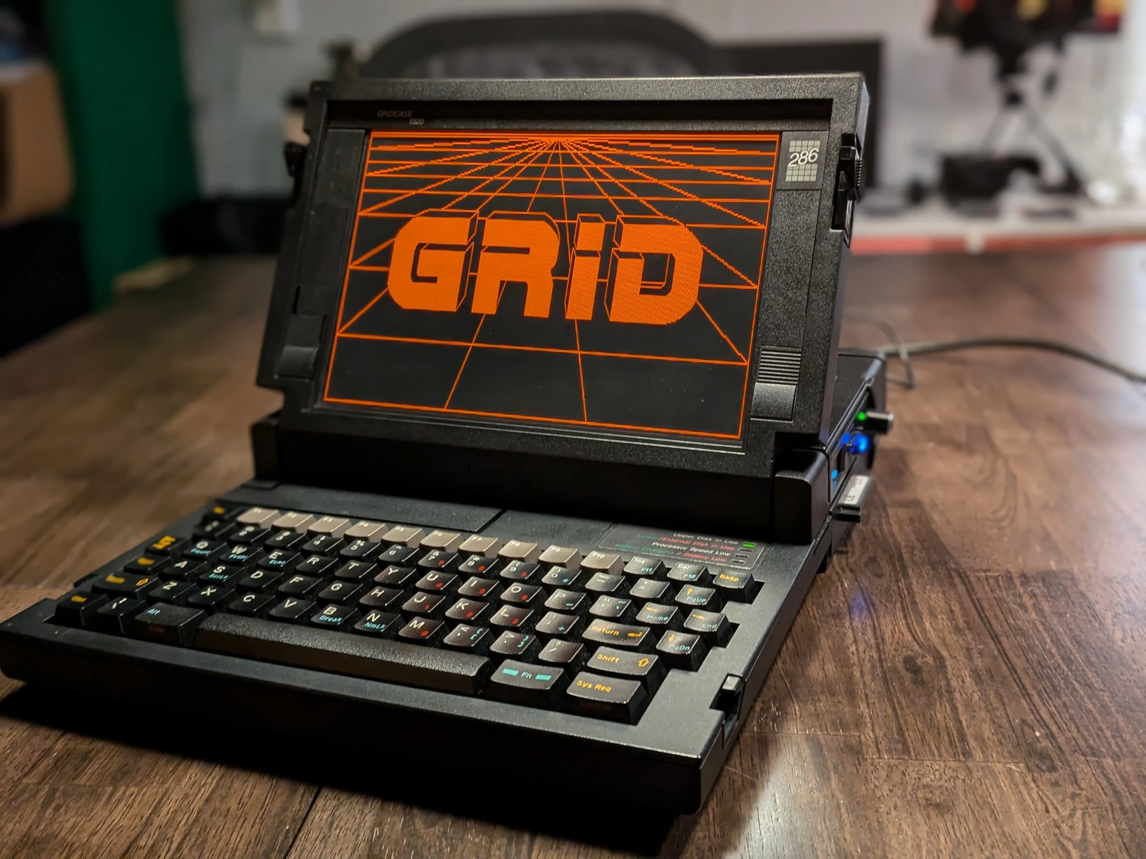
GRiDCASE 1520. Rugged 286 from 1988, magnesium alloy case, red gas plasma display. Designed for military and field use. Built to survive things that would kill lesser hardware.
Built mine from parts across three separate 1520 units. Frankenstein’s laptop, best organs of its fallen siblings.
The Three Donors
Each 1520 turned out to be a different revision. Different motherboards, different enclosures, different storage backplanes. GRiD made several configs of this machine and the parts don’t always cross over cleanly.
| Unit 1 | Unit 2 | Unit 3 | |
|---|---|---|---|
| Motherboard | Late revision, Dallas DS1287A potted RTC | Late revision, Dallas RTC replaced (aftermarket) | Early revision, Motorola MC146818AP RTC |
| RTC | Dead (sealed battery in potted module) | DS12887 replacement developed write errors (bad solder job) | Working, separate 3.6V lithium battery in tube under keyboard |
| Storage Backplane | Dual floppy (ID 20h, PN 104194-00) | Dual floppy (ID 20h) | FDD + IDE HDD (ID 90h, PN 104942-00) |
| Enclosure | Dual floppy config | Dual floppy config (best condition) | HDD config |
| IDE Support | No (dual floppy backplane) | Working | Working |
| Used For | Plasma screen donor | Case donor | Motherboard + storage backplane donor |
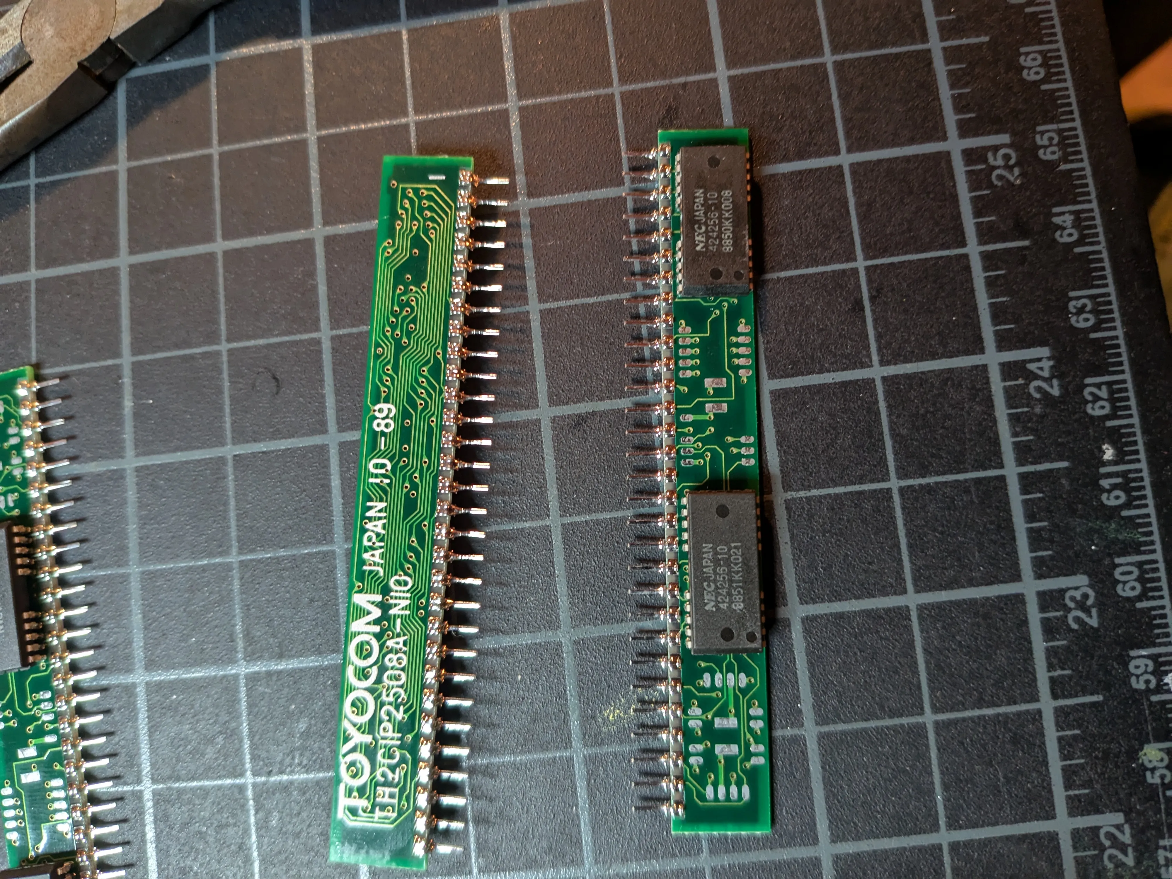
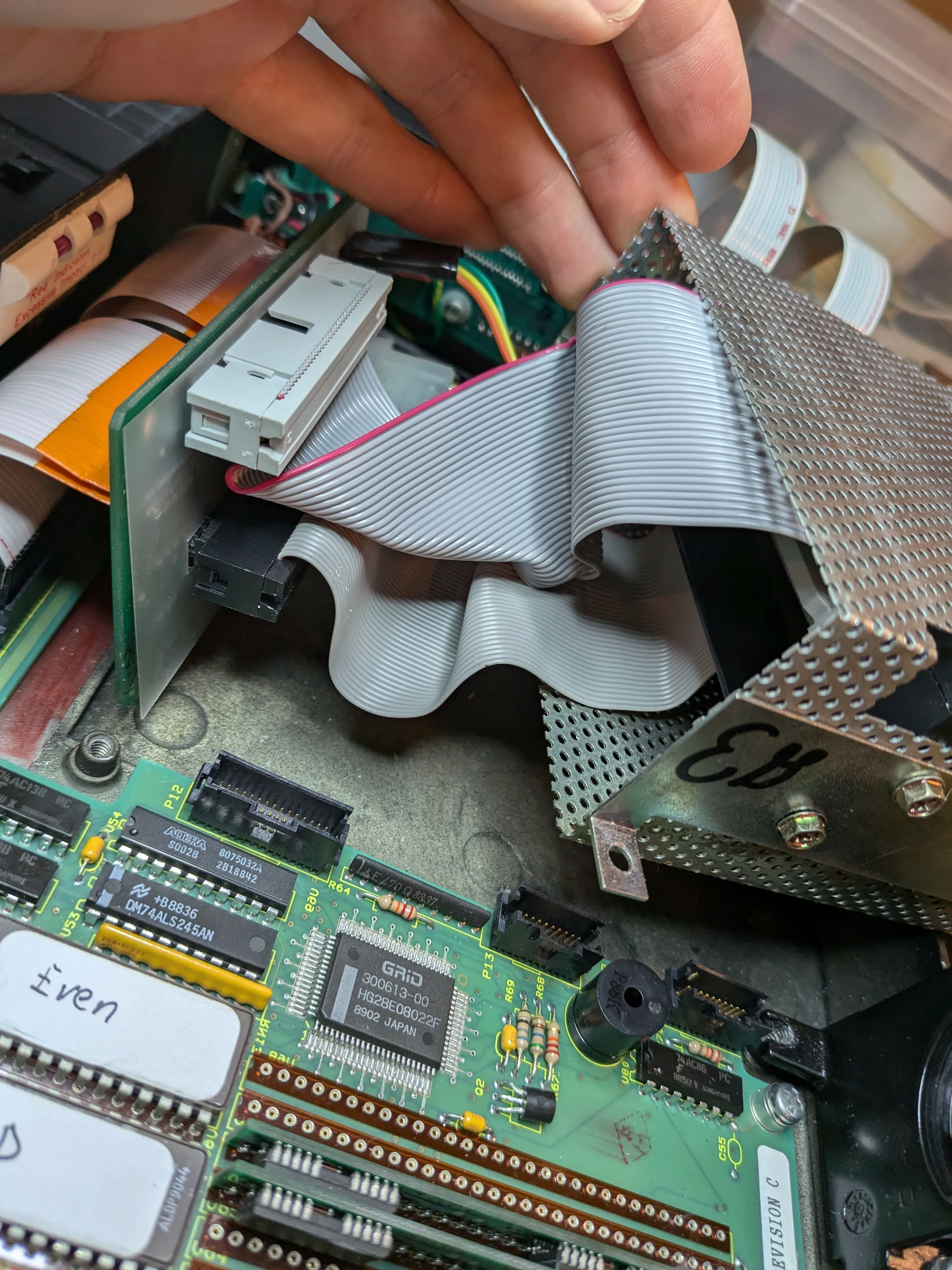
Each backplane has an ID readable from I/O port 6F8h (high nibble). The dual floppy backplane (ID 20h) uses a 74HC244 driver and 74HC273 flip-flop. The IDE backplanes carry a pair of 74HC245 bidirectional buffers for data plus a GAL for address decoding. Both connect to the mainboard via two 60-pin connectors carrying a full ISA bus plus floppy lines and GRiD-specific signals.
The final build uses the early revision motherboard (unit 3) with its FDD + IDE HDD backplane, inside the dual floppy enclosure (unit 2). The dual floppy case has an open bay where the second floppy drive would sit. Perfect for exposing the CF adapter slot for easy card swaps. HDD enclosure would have buried it behind a blank panel.
Machine Specifications
| Component | Original | Restored |
|---|---|---|
| CPU | 80C286 @ 10 MHz | - |
| RAM | 1 MB | - |
| Hard Drive | 20 MB 2.5” | StarTech 35BAYCF2IDE CF adapter + 32 MB CF card |
| Display | CGA red gas plasma | Replacement plasma panel (donor 1520) |
| Floppy | 3.5” 720K | Gotek USB floppy emulator |
| RTC | Dallas DS1287A (dead) | MC146818AP + 3.6V lithium (early revision board) |
| BIOS | GRiD/Phoenix 10/25/89 | Patched ROM via Dagwood’s RomBuster |
| Backplane | Dual floppy | HDD + Floppy backplane |
| Modem | - | WiModem232 Pro |
| OS | - | Grid MS-DOS 3.2 |
| Case | Magnesium alloy | Dual-floppy config case |
| Ports | Serial, Parallel, Keyboard, Video Out, Phone Line, External Peripheral | - |
Restoration Log
1. RTC Replacement
Knew going in the RTC would need replacing. The Dallas DS1287A potted module seals the battery inside, and after 35+ years they’re all dead. Was hoping to find an early revision board with a separate battery socket, but my first board had the late revision Dallas. Tried desoldering it and putting in a DS12887 replacement. Messed up the soldering. Board developed write errors. Had to hunt for another 1520 and either try the Dallas swap again or get lucky with an early revision. Third unit was the lucky one. Motorola MC146818AP with a plain 3.6V lithium battery in a tube under the keyboard. Pull the old battery, drop in a new one, done. No potted module, no sealed fate.
Full RTC replacement documentation →
2. Plasma Screen Swap
Red gas plasma display. That glow that makes every character look like it was written in fire. My original panel wasn’t defective, but showed some dim spots. I pulled a flawless replacement from a donor 1520.
Full plasma screen swap documentation →
3. Custom BIOS Burn
Stock GRiD/Phoenix BIOS doesn’t support non-standard drive geometries, and the Phoenix high-speed routines don’t play nice with CF adapters. Burned a patched 10/25/89 ROM using Dagwood’s RomBuster. Adds support for any HDD geometry and fast CF access. Had to apply a critical fix too; address $9763 corrected to $97DD to avoid clobbering part of the Int 18h boot error handler.
Full custom BIOS burn documentation →
4. CF-to-IDE Adapter
Swapped the original hard drive for a StarTech 35BAYCF2IDE CF adapter with a 32 MB card. Used the HDD + Floppy backplane instead of dual-floppy. Dead silent, no moving parts, and I can pull the card and read it on a modern machine for file transfers.
Full CF-IDE adapter documentation →
5. Gotek Floppy Replacement
Replaced the 720K floppy with a Gotek USB floppy emulator. Backplane floppy connectors sit on top, so the Gotek doesn’t fit cleanly with the HDD backplane. Known quirk. Just had to live with it.
Full Gotek floppy replacement documentation →
Beyond Restoration
Building GRiDCASE ROMs
GRiDCASE supports swapping in roms. Boot ROMs, diagnostic tools, burned directly into the machine. Been experimenting with building my own.
Full ROM building documentation →
References
- Reddit: Welcome to the Grid: Original post on r/retrobattlestations
- VCFed Forum: Finished restoring my GridCase 1520: Full restoration thread with discussion
- Hacking the GRiDCASE 1520 and 1530 (ClassicBits.net): Technical reference for BIOS patching, CF card support, and ROM tools
- GRiDCASE 1520 Information (ClassicBits.net): Hardware specs and documentation
- GridCase (Wikipedia): General history