Wiring and Power
2026-08-25
Three supplies, one ground
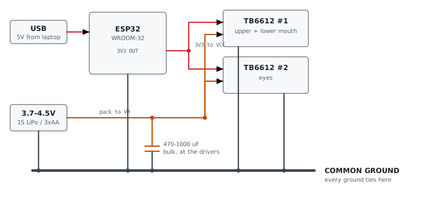
Two independent supplies, one shared return. ESP32 runs from USB on the bench, motors run from their own pack. Without the common ground the drivers see no valid logic levels and the motors sit dead or twitch at random.
Never tie VM to VCC. Never run the motors from the ESP32’s 3V3 or VIN, even though the motors are 3 V rated. The question is current, not voltage. That pin is the output of the devkit’s AMS1117, already feeding the ESP32’s own 250 mA WiFi bursts off a 500 mA USB budget. Phase 1 stalls motors on purpose and the regulator browns out mid-move.
Motor supply wants 3.7 to 4.5 V. The TB6612 drops 0.3 to 0.5 V across the bridge, so 3 V in leaves the motor short. 3.7 V in lands about 3.3 V at the winding. Don’t use the bear’s original 6 V. That fed the whole toy and the servo amplifier never put the full rail across a motor.
470 to 1000 uF bulk cap at the drivers. Motor inrush on a shared rail browns out the MCU and resets it mid-sentence. Number one failure mode for battery animatronics and it presents as random reboots.
Signal wiring
| Signal | GPIO | Signal | GPIO | |
|---|---|---|---|---|
| AIN1 / AIN2 / PWMA | 32 / 33 / 25 | I2S out BCLK / LRCLK / DIN | 18 / 5 / 17 | |
| BIN1 / BIN2 / PWMB | 26 / 27 / 14 | I2S mic SCK / WS | 16 / 4 | |
| CIN1 / CIN2 / PWMC | 13 / 23 / 22 | I2S mic SD (input-only) | 15 | |
| STBY (drivers A/B) | 21 | |||
| STBYC (eyes) | 19 |
Driver #1 carries both mouth channels. Driver #2 uses channel A only for the eyes, so its BIN1, BIN2, and PWMB stay unconnected.
Go by the silkscreen number, not the pin position. Hosyond ships both 30-pin and 38-pin ESP32 boards and the physical order differs between them.
Pins that bite
- GPIO 12 is unusable. Strapping pin. High at boot selects the wrong flash voltage and the board won’t start. Presents as a dead board.
- GPIO 0 and 2 also strap. 6 to 11 are flash.
- 34 to 39 are input-only with no internal pull-ups.
- WROVER modules use 16 and 17 for PSRAM. WROOM-32 is fine.
Keep external pulldowns on STBY and STBYC. Between reset and the first line of setup() those pins float, and a floating standby pin twitches a motor on every boot.
Motors: five wires, use two
Each plug carries 2 motor wires (the pair with suppression capacitors across them) and 3 potentiometer wires. Only the motor pair goes to the driver.
Tell them apart in thirty seconds. The motor pair reads 2 to 30 ohms and twitches on a brief touch of a cell. On the pot, the two outer wires read a fixed value that doesn’t change as you turn the mechanism, while each outer-to-wiper reading sweeps smoothly and the two always sum to that total.
Expect a motor to run backwards. Swap its two output leads, or flip the offset constant in the firmware. The mouth needs upper and lower opposed, so at least one very likely needs it.
Potentiometer feedback
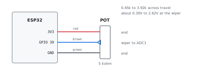
| Pot wire | Goes to |
|---|---|
| red (end) | 3V3 rail, shared by all three |
| green (end) | GND rail, shared by all three |
| upper wiper (brown) | GPIO 34 |
| lower wiper (brown) | GPIO 36 |
| eyes wiper (brown) | GPIO 39 |
Only the wipers need their own pin. Three pots draw 2 mA total. Pot reads 0.45k to 3.92k across travel, about 0.30 V to 2.62 V at the wiper.
3.3 V only. Pot ends go to 3V3 and GND. Never 5 V, never VM. The wiper feeds an ADC input directly and anything above 3.3 V damages it. Get this wrong and the pack back-feeds into the board through the divider, half-powers the ESP32, and it stops booting.
Why these pins: ADC2 is unusable while WiFi is running, so wipers must land on ADC1 (GPIO 32 to 39). 34, 36, and 39 are also input-only, which suits an analog input and costs no output pin.
Before you power on
- Meter continuity between the grounds. ESP32 GND to each driver’s GND should read a short. Most common cause of “the motors do nothing”.
- Meter VM against VCC. They must not be connected.
- Check the electrolytic’s polarity. Stripe is negative, goes to ground.
- Power the motor pack first, USB second. Watch for the ESP32 resetting when a motor starts. That’s the brownout the bulk cap exists to prevent.
- Watch the first home. A bench supply would catch a miswired H-bridge by current-limiting. Batteries won’t.
Bench gotchas
- Motors couple EMI into the console UART. Framing errors mid-transmission during drive. Firmware drops indented input so its own output can never parse as a command, and flushes RX after every move. Keep motor leads away from the USB cable and twist each pair.
- The gearbox can’t be back-driven by hand. High reduction. Use the sweep command, which drives the motor and samples the pot together.
- Seized servos are the classic failure on these bears. Forty years of hardened grease. Working the mechanism by hand frees them.
- Console needs RTS and DTR held low. On this devkit RTS drives EN and DTR drives GPIO 0. A terminal that asserts them on open holds the board in reset or download mode and you read stale USB-serial garbage on an exact 32 byte period.
python3 -m serial.tools.miniterm --echo --rts 0 --dtr 0 /dev/ttyUSB0 115200References
- Wiring reference in the repo: same content plus a self-contained HTML version with a tick-off checklist